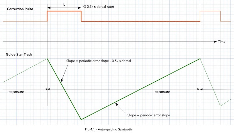
OK, we shall start at the sawtooth graph. If each detail of the graph has not yet sunken in, keep studying it. Once you grok it, all guiding problems can be explained away.

The green part of the graph shows the path of a guide star while you are exposing it. The top red part is the suide pulse.
Notice that the pulse does not suddeny move the mount. It slews the mount at the guide rate (shown as 0.5x sidereal rate here).
Second thing to notice is that the of a guide star will always move (i.e., take the path of that green line). The centroid measurements will always lag the star, and when the periodic error slope is high., this lag makes traditional guiding inaccurate and that is what I am writing the white paper about (to show how to obtain a pulse that corrects in spite of a lagging centroid, and yet be a stable feedback loop -- yeah, you need some rudimentary knowledge of z-Transforms to fully understanf the white paper).
For smooth mounts, the slope of the periodic error is small, and the approximation of using the centroid is good enough.
The guide star will actually move by the the peak-to-peak of that sawtooth.
Now, the leading edge of the sawtooth is a self-inflicted wound! I.e., the reason the green line moves downwards is due to the Correction Pulse. This will cause the guide star to move down at the rate of the guide rate as long as the pulse is being applied. Once you let the foot off the correction pulse, the green line now takes the path that is determined by the slope of the periodic error. This is where the slope of the periodic error comes in -- if you knon't know the worse case slope, you also don't know how much to limit the value N (the max duration of the correction pulse).
Now, if you stare at the leading edge of the sawtooth, you will see that the slope is not precisely the guide rate, but the guide rate minus the slope of the periodic error. This is because the periodic error is constantly being applied, even when we are applying a correction pulse.
Now you can see why shoetening the exposure time (higher guide frae rates) help. When you shorten the expose time, the trailing edge of the sawtooth shortens -- the consequence is that the height of the sawtooth is also proportionately shortened.
That is why, if you have a good guide scope, the first thing you do to strain wave geared mount is to reduce the exposure time to 0.5 seconds! I was emperically playing with my RST-135 a couple of years ago and found that out, but the real explanation did not dawn on me until I modeled the mount dynamics as the above sawtooth (the sawtooth explains everything! :-).
In those days, the ASIAIR was not able to achieve 2 FPS even when you reduced the exposure time to 0.5 seconds, and we could never guide an RST-135 properly with ASIAIR. I pleaded with ZWO, all the way to the top, and the 2 FPS rate was not possible until mid of last year, and I suspect it was because they needed 2 FPS also for their own mount, not because they had wanted a better guiding experience for their customers.
The reason you want to limit the correction pulse duration is bacuse you don't want the autoguider to react to something else that is not caused by the perioid error (just like the shaft encoders will also ignore wind gusts, owls, etc). The autoguider will still react to wind gusts, etc, but at least we now know how to maximally limit the error.
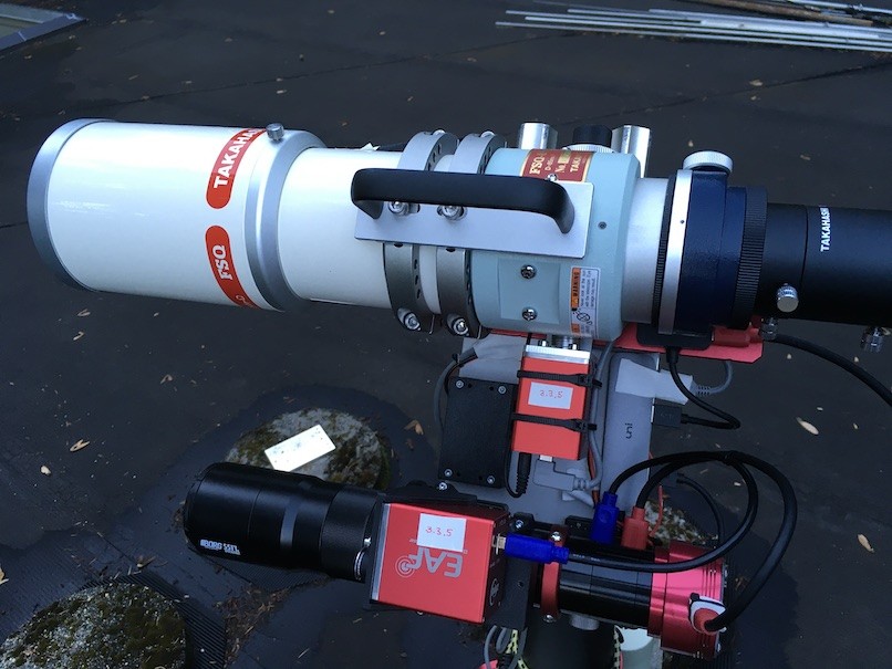
So, two things you can do for now (unless you also enjoy writing code for autoguiding) are: (1) limit the max RA pulse duration, and (2) use the highest FPS guduing as you can get away with (a lot of you know that I don't use an OAG, but have largish guide scopes on the dual saddle plate of my RST-135; and now you know why :-)

The guide scope is made up of a Borg 55FL objective, and the guide camea of choise so far is the ASI178MM. The dual saddle plate is 10 mm thick, and hides the RST-135 from view in the above photo.
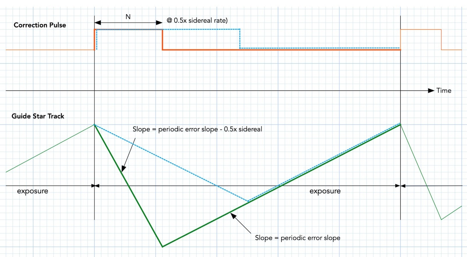
OK, we now go to the third thing that might also help. That "dashed blue line" afterthought that I thought of just a couple of days ago.

Notice that if we were to slow down the guide rate, we would be stretching the correction pulse (the dashed blue that is superimposed on the red pulse). At the same time, we would be applying a gentler slope to the leading edge of the sawtooth (ah, the sawtooth again :-). Remember what I mentioned above that the slope of the leading edge is not just the slope of the guide rate and the perioic error slope?
Well, look at how it helps us in the dashed blue sawtooth that is superimposed on the green sawtooth -- It has compressed the peak-to-peak value of that sawtooth!
If you stretch the dashed blue all the way to cover the exposure time, the guide rate is now exactly the same magnitude (but opposite in sign) as the periodic error slope of the mount, and you have the smoothest guiding possible -- this is what I have eaerlier pesented a a different guding paradigm, where you are not pulse width modulating the correction pulses, but pulse amplitude modulating the correction pulses.
https://www.elprocus.com/pulse-amplitude-modulation/
Even the worst mount in the world can be calmed down. But as I said, for the forseeable future, you'll have to brew your own code (I have not even formally released my white paper yet -- I can post a like here when it is ready, if there is enough interest -- or email me directly if you want to help proof read it).
Notice in all of the above that the peak-to-peak PE does not ever come into play for auto-guiding (it is only useful for visueal if you want a target to be within the FOV of the eyepiece). Everything with autoguiding is affected time derivatives (slopes). Even down to the guide rate. Find a mount that has small derivatives for the periodic error curve, and you will be a happy person (or just implement the Pulse Amplitude Modulation scheme :-).
Chen