ASIMount@ZWO the user makes the guide move every 2.8-3.1seconds, does it mean almost 0.98-1.09 arc-sec(on one Axis) on average?

The rate is about .35 arc-seconds per second (of time). So, if you do't issue fast enough correction pulses, you will need a longer gulde. However, if you wait 3 seconds before issuing another guide pulse, that means that mount has moved by itself for 1 arc-second before any corrective measure is taken.

Accumulating 3 seconds worth of error on a strain wave gear mount is way too large for good guiding! At that drift rate, and correcting only every 3 seconds will cause that axis' RMS error to be a whopping 0.7 arc seconds! I don't think a user would tolerate that mucg guiding error.

This is why it is imperative for strain wave geared mount to use very rapid correction rates. As I mentioned at the end of my previous post, it is not the camera exposure rate (FPS) that is important, it is the correction rate.

Exposures (i.e., sampling the centroid) can actually be done at a rate even slower than 0.5 FPS (2 second exposures). But the correction rates need to be fast.

It is just that with today's PHD2 (and ASIAIR) guiding, we can only issue one guide pulse per exposure. And because of that we have no choice today but make very short exposures (I need 0.5 second exposures with an RST-135 to guide it at 0.4 arc secnd total RMS).

For example, you can take a 2 second exposure, compute the centroid positionand issue 4 correction pulses that are separated by 0.5 seconds between that exposure and the next exposure. If you also estimate the first derivative of the centroid changes, you can actually issue predictive pulse widths, and get the error to drop below 0.1 arc second between exposures in my simulations.

Ask Andy Meng or Walf Wu to send me an email (they have my email address) if you are interested, and I can send an Xcode project that I have started to work on to simulate such behavior.

Since I never have access to ASIAIR source code, I will be testing this in INDIGO with my RST-135, and perhaps a Nyx-101 if I pick one up.

Chen

    Here are some figure that I had recently sent to Rumen and Peter (the two principals of Indigo) showing the problem and solution.

    The first image shows the typical situation today (one correction pulse per exposure):

    As the slope of the PE gets large, the pulses also had to be much longer, and at the same time the actual RA tracking error has a larger error. The main imaging camera will see a star move in RA according to the "actual RA track." Notice that the RA track zig-zag. It "zigs" during the correction pulse, and "zags" because of the mount's PE.

    The only way today to improve the RA tracking error in ASIAIR is to shorten the exposure time.

    Now, imagine being able to distribute that one pulse per exposure to two pulses per exposure:

    Notice that the actual RA tracking error is now smaller (by a factor of about two). The pulses are shorter, but there are more of them. The total area under the curve of the pulses is actually the same as the one pulse per exposure case.

    Increasing to 4 pulses per exposure etc will keep reducing the peak RA track error. And 8 pulses per exposure time, even better, etc.

    Until in the mathematical limit, we use different guide rates for each exposure duration), instead of using a constant guide rate (0.5x sideral) and different durations:

    The RA tracking error is now maximally flattened. The only way to get flatter is to again shorten the exposure duration :-). This ultimate solution ("guide by rate") may not be possible with all mounts (because some of them only have a limited number of guide rates), but in the RST-135, I can control the guide rate in units of 1/100 of the sidereal rate, from 0.01x to 0.99x sidereal rate. But most mounts should be able to handle the "N-pulses per exposure" model. Even with 2 pulses per exposure, we already impoved today's RA tracking error by a factor of two.

    Chen

      w7ay thank you for taking the time to cover this topic as hopefully this will improve the asiair and AM5 ecosystem. I am finding that base settings of max duration of 2000ms at 1s exposures seems a bit large but coming from a gem mount with typical 2-3s exposures I have been scouring the web for guidance and better understanding. I see a lot of people using 70-100% agression with 2000 max durations at 1s exposures with AM5 mounts but see that when I do that with anything but great atmosphere conditions, my guiding is all over the place and choppy.

      Is it still better now to use 700-1000ms max durations with lower 30-45% agression at 0.5-1.0s exposures even now (until ZWO figures a way to provide multiple pulses per exposure), instead of having to now use larger 2000ms moves and higher aggression in single pulse per exposure.

      Any settings help in regards to max duration, aggression, exposure lengths would be appreciated as I am a novice when it comes to fast guiding. My mount PE error is 16.8/6.0 on RA but it seems to have a secondary harmonic in the graph too. Thanks in advance.

      • w7ay replied to this.

        w7ay again, thank you so much for your contribution to this and many other topics as your knowledge and effort is trully appreciated and has been extremely helpful!

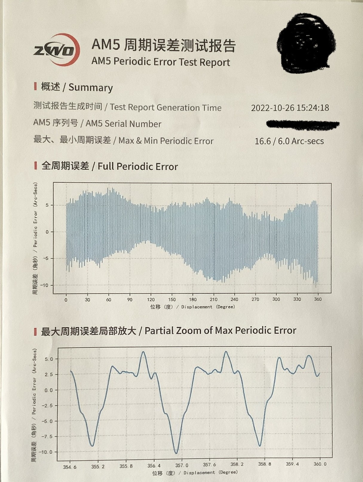
        Kevin_A My mount PE error is 16.8/6.0 on RA but it seems to have a secondary harmonic in the graph too.

        Many harmonics, not just second. A second harmonic would have looked like a fundamental sine wave where each half cycle is displaced up and down also in a sinusoidal motion.

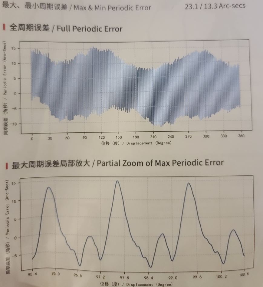
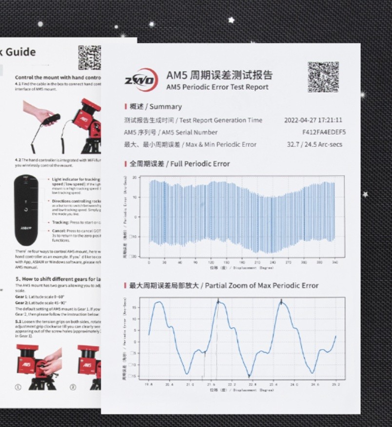
        It is too bad that ZWO does not provide numerical data for the PE curve, just some plots, otherwise we could take a Fourier transform and actually look at the harmonic content.

        Notice in the second figure ("partial zoom") that you posted, the cycles don't even repeat. So there are even sub-harmonics present. The peaks of that last cycle is distinctly different from the previous two, and those two don't look perfectly alike either. This is characteristic of strain wave gears, and is caused mostly by the flexible (yep, flexible :-) spline gear component of the strain wave gear. The better machined the gears are, the more repeatable the cycles are. But there is always a slop.

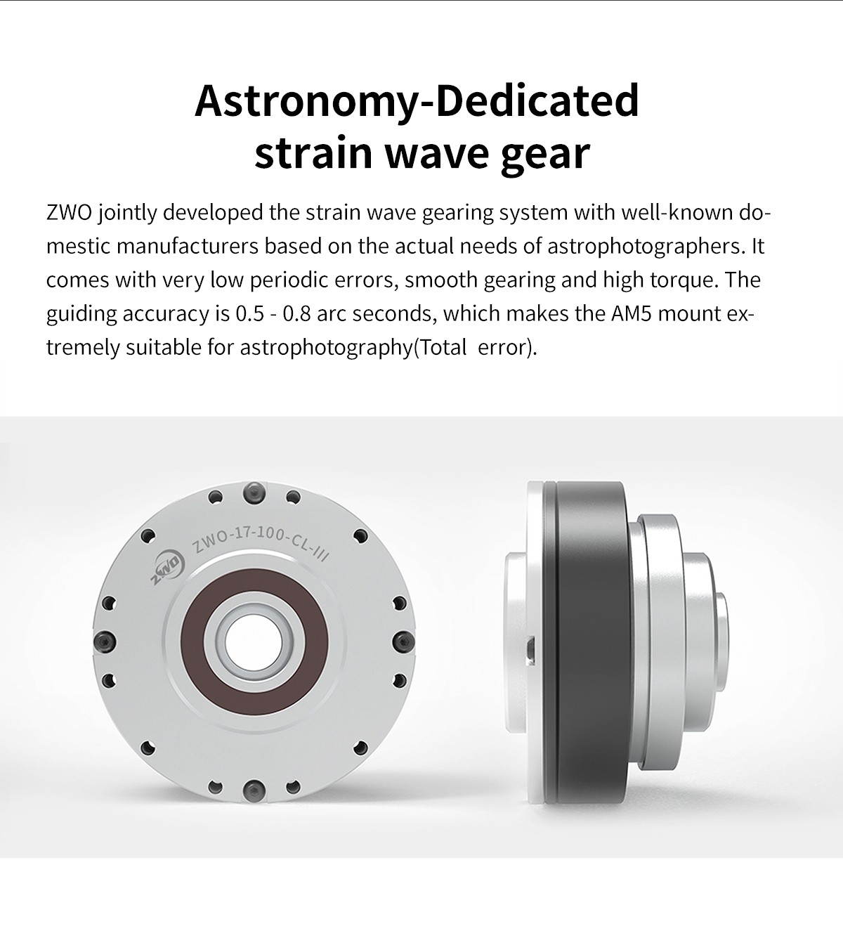
        Take a look at the GIF image in this wiki https://en.wikipedia.org/wiki/Strain_wave_gearing . The flexible spline gear is the red gear in the image.

        This, by the way, is the reason why you cannot create a fixed periodic error correction (PEC) for strain wave mounts. People are clamoring for PEC, without understanding that it simply is not mathematically possible ("unmöglich", or as the Japanese engineers put it... "verrrrry difficult") to use a single cycle to correct. (You can use some predictive methods, but then, you might as well just guide a strain wave mount the way they need to be guided -- with rapid guide updates).

        Since there is no numerical data, we will just bypass the harmonic analysis and just wing it and estimate the worst case slopes directly from the figures as best we can.

        The scale (in degrees of the shaft) of the abscissa is not very useful for us, but we know that each cycle of the PE correcponds ro one sidereal day/200 (in the case of your mount; since they had tried to mimic the RainbowAstro RST-150h and RST-135). That is about 480.82 seconds, which I have drawn in red.

        Now we try to eyeball some part of the curve that has the largest slope (just don't tell my engineering profs that I am winging it like this, or they would retroactively flunk me)...

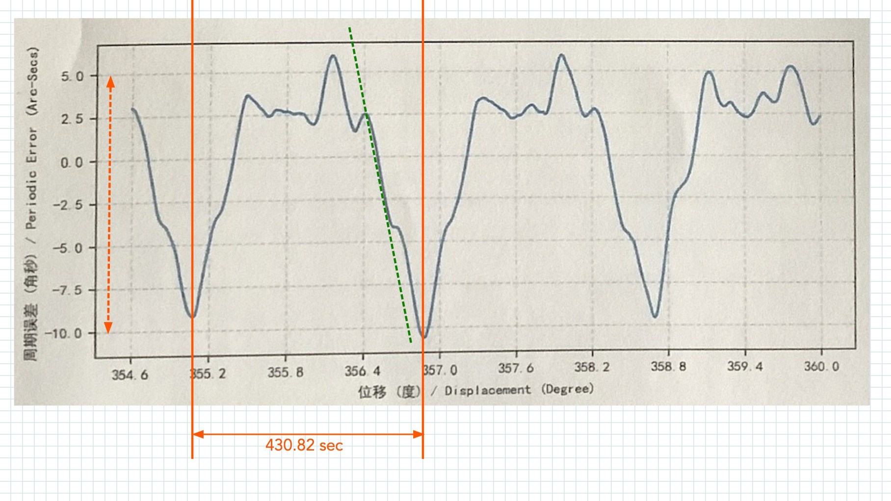
        The dashed green line is probably a good enough pick.

        I am doing this using an application on macOS called EazyDraw, and it is nice enough to show the actual coordinates:

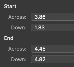
        So we know the slope of that line is dy/dx = (2.99/0.59) = 5.07 in the EazyDraw units. To estimate real units, I took the distance between -10 arc seconds and +5 arc-seconds in the ordinate of the graph (dashed red line), and that came to 2.43 in the EazyDraw units. So we know that the vertical scale is 15 arc seconds per 2.43 EazyDraw units, or 6.17 arc-seconds/EazyDraw units.

        Similarly, the distance between the 430.82-second lines is 2.18 EazyDraw units, so we know the scale of the abscissa is (430.82/2.18 ) = 198 seconds per EazyDraw units.

        We had come up with a slope of 5.07 EazyDraw units, so applying these scales, we get voila, a worst case slope of ( 5.07*6.17/198 ) = 0.16 arc-seconds per second.

        A perfect sine wave with 15 arc-second peak-to-peak amplitude would have given you a worse case slope of around 0.105 arc-seconds/second. So, indeed your mount has about what is called 60% total harmonic distortion (THD) in that waveform (the audio amplifier in your TV probaby has a THD of less than 0.1% :-). If this were audible, it would sound rather dissonant -- in fact, you can probably tell when you slew the mount that the sound is not like what you hear from a tuning fork [which is quite sinusoidal] :-)

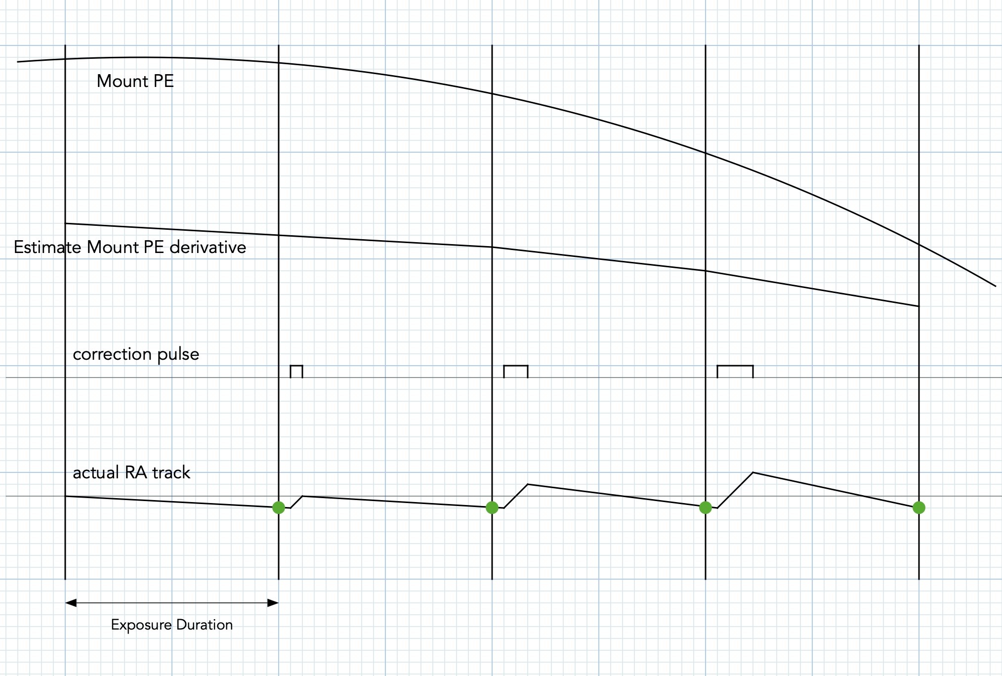
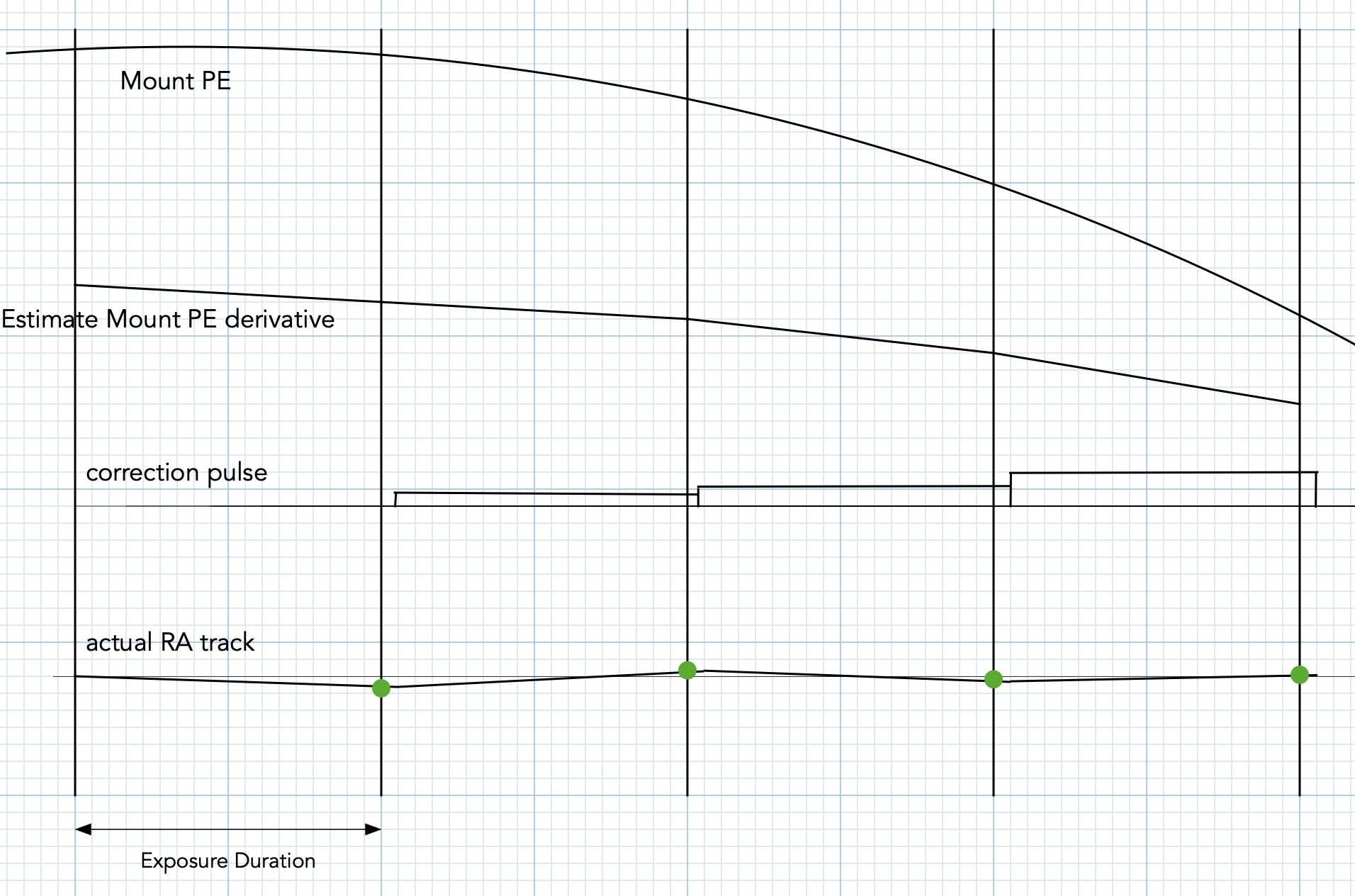
        If you want the peak error (from one axis) to accumulate less than 0.1 arc-seconds before applying a correction pulse, you will need to apply correction puses no longer than 1 per second. And, for PHD2 guiding, that means a guide exposure time no more than 1 second.

        You have one of the better ZWO mounts. If you look at their documentation, you will find mounts that have much higher peak-to-peak error than the 15 arc-seconds in your mount. Here is a sampling from their documentation:

        https://astronomy-imaging-camera.com/wp-content/uploads/all-kinds-of-periodic-errors.jpg

        The one on the top right has a peak-to-peak PE that is almost three times your mount's p-p PE. For people who have those mounts, they would need more correction pulses per second than you do.

        However, the devil is in the details. ZWO did not show the per-cycle curve, so we don't know the actual harmonic content.

        They do have a picture that showed this:

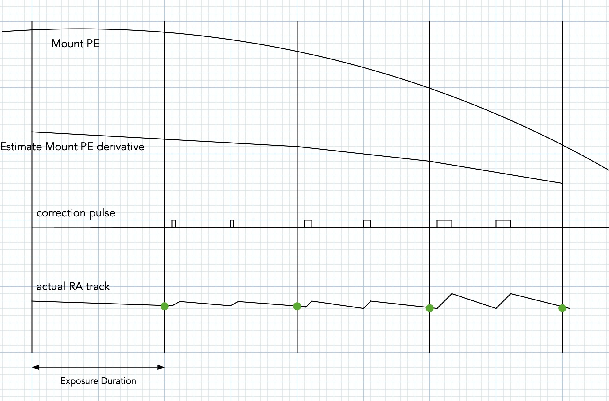
        Notice that the worst case slope looks worse than yours too. And if you stare closely at the scales, it looks like the p-p error is perhaps around 30 arc seconds (much worse than yours, unless the "partial zoom" plot for your mount came from a favorable part of the 360º travel). So, compared to your mount, that particular mount would be harder to guide and would need guide corrections in the 2 per second (0.5 second exposures) region to get anywhere close to 0.5 arc-second total RMS.

        With care, and studying and understanding your mount, you can auto guide these strain wave mounts. You just can't use some lazy "what is your settings because I want to copy it" method, because the characteristics are so different from mount to mount that comes off the same assembly line.

        So, please folks, don't use the numbers that are derived above if you are not @Kevin_A.

        I can get better than 0.5 arcsecond total RMS error with my RST-135, and at times, when the gears are at the smooth part of the curve, I would get 0.25 arcsecond total RMS type guiding. In my case, I use 0.5 second guide exposures, and set my max RA and max declination durations in the 130 ms to 180 ms region (forget the 1000ms to 2000ms nonsense, folks), and setting aggressiveness down in the 35% to 45% region. But not even all RST-135 are alike. I have two RST-135, and they are not alike.

        Chen

          w7ay thank you so much for the detailed explanation.
          I am using asiair to run this AM5 mount and will be using 1s exposures and will now lower both my agression settings below 40 for some testing. I will also try lowering the duration time too around 300-500 and give it a test. This should be better if I understood correctly. I also could not figure out how any mount running 1s exposures could have a 2000ms max duration setting per exposure as that would overlap the next exposure!
          Once again thank you Chen, your time, knowledge and effort is greatly appreciated!

            Kevin_A Once again thank you Chen, your time, knowledge and effort is greatly appreciated!

            No sweat, Kevin.

            The major take-away should be that the amplitude of the Periodic Error curve for a strain wave geared mount is only important for visual observers, who want to keep a object in the view of their eyepiece.

            The perodic errors for these gears are too large for long exposure astrophotography where you must auto-guide anyway.

            When auto-guiding, it is the amplitude of the first derivative ("slope") of the periodic error curve that determines how easy the mount is to guide. Not the amplitude of the curve itself -- the amplitude of the curve itself is simply a scale factor of the first derivative of the curve.

            The harmonics are more insidious.

            A second harmonic that is 50% will contribute as much to the slope as the amplitude of the curve itself. A third harmonic that is just 33% will also contribute as much to the derivative, 25% of 4th harmonic, 20% of the fifth harmonic, etc.

            I.e., if you start with a clean perioidic error curve with amplitude A (i.e., peak-to-peak error of 2A), and you add a 50% second harmonic term, it will be as bad as another mount that has no second harmonic, but has a periodic error amplitude that is twice as large to start with.

            And the terms accumulate. So, a mount with 33% third harmonic, plus 20% 5th harmonic, will have a worst case first derivative that is 3 times that of a mount that has a clean periodic error curve, when both start with the same fundamental frequency amplitudes.

            The more irregular the curve looks to the eye, the scarier it is to guide.

            Mounts that have high harmonic distortion will often guide really well, and then suddenly (when the shaft reaches the place with large PE slope) go bonkers for a short while, because the correction pulse rate is not keeping up with the slope.

            One day, we will be able to develop better software so that these high first derivative mounts can be tamed (for example, with one of the two schemes that I described earlier). Until then, unless you write your own code, be careful what you buy in the strain wave mount market. I am myself currently on hold waiting for actual numbers from the Pegasus Nyx -- I am looking for a mount with a little more payload capability than my RST-135; the RST-300 is overkill and will kill my back :-).

            Chen

              ASIMount@ZWO [w7ay]
              Maybe we can attach the fourier transform of the Full periodic error data if you guys really want it.

              It won't be for me since I am not in the market for a AM5 mount. But I am sure someone else out there would be interested.

              A Fourier transform for a full 720 degree shaft rotation (remember that a strain wave gear has that 2x property) would be useful since we can also check the precision of that flexible spline.

              So far, I have only seen curves of the Harmonic Drive gears (like the 1991 NASA conference paper that I linked to earlier); it would be interesting to see how the flexible spline in the gears that ZWO uses performs.

              If you are using an FFT to estimate the Fourier transform, be sure to window it properly unless the full double-cycle is a power of two.

              By the way, this is a link to the full PDF of that paper:

              https://ntrs.nasa.gov/api/citations/19910015306/downloads/19910015306.pdf

              Chen

              ASIMount@ZWO Maybe we can attach the fourier transform of the Full periodic error data if you guys really want it.

              BTW, please keep in mind that the magnitude of a Fourier transform will be putting out the average harmonic distortion number. And with no phase information, we would not know what the worse case first derivative is.

              Have you kept the original data for each mount? If so,the first derivative of that curve would be extremely useful for determining the pulse correction rate that is needed to keep the actual tracking error small for that particular mount -- it could be more useful than a Fourier transform.

              Or even just a single number can already be very useful -- max second derivative over the entire rotation, in units of arc-seconds/second of time.

              Chen

              w7ay The more irregular the curve looks to the eye, the scarier it is to guide.

              Mine looks pretty tame, comparatively, yet I'm having the hardest time guiding. Does anything in my report jump out as a possible issue? If my math is correct, I need to correct at a rate of 0.107 arc-seconds per second. My imaging scale is 2.25"/px, and guiding scale is 2.48"/px. Both are very close in scale, so setting min-mo in PhD2 to 0.04? Do aggression settings figure into this at all?

              • w7ay replied to this.

                KC_Astro_Mutt Do aggression settings figure into this at all?

                Aggressiveness value is basically the classical "loop gain." Apply too little and there is a larger residual error (e.g., the RA corrections not keeping up), apply too much, and the loop starts being unstable (e.g., the RA corrections, once started, can end up making large oscillations).

                See https://en.wikipedia.org/wiki/Loop_gain among many other places.

                Mine looks pretty tame, comparatively

                Unfortunately, yours also start off having (1) a peak-to-peak Periodic curve that is twice that of Kevin's, and (2) your mount has a huge second order harmonic (see the double peaks in the second figure? The second harmonic is so large that it flipped the direction of half of the peaks!). That basically make the 430 second period appear to be perhaps (eyeballing) 2/3 of what it should be.

                Just those two factors put together could make your mount's worse case slope twice as large as Kevin's.

                Consider this too: in Kevin's case, the large slopes appear four times per 430 seconds (two positive, and two negative slopes). Because of your mount's multiple humps, you are seeing eight places where the slope is large. So you could be seeing large RA guide errors very often, like every 50 or 60 seconds. Depending on how long they last, they may not register in the main camera's image, but it means that you are bound to have at least one large excursion for every subframe that you take that is more than 60 seconds long.

                yet I'm having the hardest time guiding

                Seeing your mount's PE curves, I am not too surprised that you have problems. Try starting with a 0.5 second exposure rate since I think your mount might need it (don't use anything longer than 1 second), find a camera that can give 2 FPS guiding (that is harder to do in ASIAIR v2.0 and earlier, but should be easy to achieve with a laptop and PHD2; ASIAIR v2.1 Beta has improved the guide FPS).

                Start with low aggressiveness and a max pulse of less than half of the exposure (i.e., start with perhaps 200 ms max pulse or so -- only increase that value if you find that the guiding cannot keep up with the mount PE even with increased aggressiveness; try increasing aggressiveness first before increasing the max pulse). Remember that RA and declination have different gears, you will need different parameters with them.

                To use short exposures, you will need to turn on multistar guiding, or "seeing" will eat you alive. If all guide stars have about the same SNR, using 2 stars is equivalent to doing 2 second guide exposures instead of 1 second. 4 stars is equivalent to 4 second exposure instead of 1 second (etc). You guys who have taken Probability Theory will recognize this a "Ergordicity" (in simple terms, ensemble averages is the same as time averages). In practice, not all stars have the same SNR, so 2 star guiding many only be 1.5x better than 1 star guiding, etc, and with further diminishing returns as you add even more stars.

                As to MinMove, it will not help if the errors are not unidirectional (i.e., for the declination if you are perfectly polar aligned, and no declination drift, and there is a large backlash).

                Backlash is not a problem with RA if you you keep (guide rate x guide pulse width) below the sidereal rate. This is because the mount is already tracking at 1x sidereal rate, and a correct pulse that is 0.5x sidereal rate) in the opposite direction (that is not too long) is simply a process of slowing down the motor for the duration of the pulse. For this reason, never ever make the max pulse duration of RA ever, ever close to 2 seconds when the guide rate is 0.5x sidereal. Or 3 seconds if the guide rate is 0.33x sidereal, etc. Once you know this, it should be obvious, but it is seldom explained, and most people figure it out themselves. If you remember, I was very vehement when I saw stuff like 2000ms being recommended as a max pulse rate for the RA direction.

                Good luck.

                Chen

                  Thank you Chen! Your analysis is much appreciated. I hope I can get PhD2 to tame this thing.

                  w7ay Unfortunately, yours also start off having (1) a peak-to-peak Periodic curve that is twice that of Kevin's, and (2) your mount has a huge second order harmonic (see the double peaks in the second figure? The second harmonic is so large that it flipped the direction of half of the peaks!). That basically make the 430 second period appear to be perhaps (eyeballing) 2/3 of what it should be.

                  What are your thoughts on my chances on guiding with this mount, with that PE? Is it doable?

                  • w7ay replied to this.

                    KC_Astro_Mutt What are your thoughts on my chances on guiding with this mount, with that PE?

                    Sure, anything can be guided.

                    The question is what did you expect from it when you'd checked the specs and bought it.

                    Are you looking for 1" total RMS error from this mount? Very likely it can do it. Are you looking of 0.5" total RMS error? Perhaps it can. Are you looking for 0.25" total RMS error? Perhaps not.

                    Also, remember that the RMS (root mean square) values are long term averages. You will likely see occasional (and in your case, twice as often as Kevin's mount) spkes of larger than the RMS values (peak values are always no smaller than the mean value).

                    If those spikes have short durations (like lasts only 1 or two seconds), they are not likely to show up in your main camera images (although your is twice the problem of Kevin's) if they don't repeat often.

                    Stain wave geared German mounts would usually be outperformed by a legacy worm-geared German mount that are a quarter their price when it comes to guide precision.

                    When you buy a strain wave geared mount, you are paying for portability, not for accuracy. I really wish the vendors and dealers would temper the customers' expectations, instead of getting their shills to tout these mounts. They are not for everybody -- they are for people who desire more portability, and don't mind paying more for the portability (and be willing to have guide experiences of a mount a quarter the price). The strain wave gears' good attributes are somewhere other than guiding. An AZGTi for example can probably guide better than your mount, but it cannot sling a heavy paylod around, and it will always need time to balance every eveing.

                    Touting "small peak-to-peak PE" to astophotographers for example, is just plain misleading; since PE amplitude is not the root problem for guiding, the first derivative of the PE is. A mount can have low peak-to-peak PE, and yet guide terribly because it has large harmonics.

                    The old maxim for good guiding is to have a (1) long PE period, and (2) a smooth curve (i.e., very low harmonics). That hasn't changed -- I have simply pointed out that one way to get around a non-smooth mount is to produce higher guide pulses per second, and that you can do this even without exposing for shorter times (just cannot do it with PHD2 today, unless you write your own code to replace PHD2 for guiding).

                    Chen

                      w7ay The question is what did you expect from it when you'd checked the specs and bought it.

                      I expected the advertised .5" to .8" rms. No better, no worse. .9" or less would be fine though.

                      • w7ay replied to this.

                        KC_Astro_Mutt I expected the advertised .5" to .8" rms. No better, no worse. .9" or less would be fine though.

                        Just start by keeping the max pulses short and 0.5" guide exposures (checking to see that you can get 2 FPS correction updates) and see where you can go from there.

                        Perhaps you can return it, if they really claim definitively that the mount can guide better than 0.8" total RMS, and your mount cannot even get close.

                        Again, keep in mind what I mentioned about RMS being the time average of the error. The peak errors from your mount will be larger than the RMS average, and you didn't mention if they had also assured you that the peak error will remain inside 0.8".

                        When tuning your guide parameters, remember to treat the RA and Declination axes separately. Their error and harmonics are probably wildly different. Tune one first until you are happy with it, and only then tune the other.

                        Chen

                          w7ay erhaps you can return it, if they really claim definitively that the mount can guide better than 0.8" total RMS, and your mount cannot even get close.

                          From the product description:
                          "Another huge benefit of harmonic drive mounts is that they have zero backlash, which traditional worm drive equatorial mount owners know can be an issue even in the best mounts. Though harmonic drive mounts do suffer from some periodic error, ZWO has made sure that the AM5 has less than ±20 arcseconds, and each mount comes with an inspection certificate to prove it. When autoguiding, the accuracy is an impressive 0.5 to 0.8 arcseconds."

                          • w7ay replied to this.

                            KC_Astro_Mutt ZWO has made sure that the AM5 has less than ±20 arcseconds

                            That (40" peak-to-peak PE) has nothing to do with whether the mount is easy to guide. You need the first derivative of the PE.

                            Notice that Kevin's mount is around +8" to -15", and he apparently is already not having an easy time. Yours is +15" to -8" and you are having problems.

                            I can claim that my mount's color is matched to Pantone silver to within 0.5 ∆E, but that has equally nothing to do with how easy or hard it is to guide, either.

                            Caveat Emptor.

                            Chen