Getting the best performance from my AM5
- Edited
kaiyung 3) this app is really easy to use and has an intuitive GUI
How did you get to the "Drift corrected" and "Frequency Analysis". I looked around and could not get those graphs generated in phd2 log viewer.
Also did you issue correction during that period or you just let the mount track by turning off the guide function in phd2?

kaiyung
Hi kaiyung,
We've received your email.
Just checking the status, are you mounting your AT72edII and SvBony guide scope on the self-made wood dovetail plate?
- Edited

Dave, Kai, Mike, Kevin, et al,
While writing the white paper on "how to guide unguidable mounts (:-)", something else just hit me like a ton of bricks.
Remember that sawtooth that describes the dynamics of guiding?
The amplitude of the sawtooth determines the limit of how well you can guide. If the sawtooth is 0.3 arcsec peak to peak, for example, you are not going to be able to guide better than that.
The leading edge of the sawtooth has a slope equal to the slope of the periodic error minus the guide rate.
Now, if the slope of your periodic error is less than say, 1.9 arcsec/second, you can use a slower (0.25x sidereal) guide rate and reduce the amplitude of that sawtooth! It almost certainly is; I have yet to come across a strain wave gear mount that is that poor. But you folks know your numbers, so you know for sure.
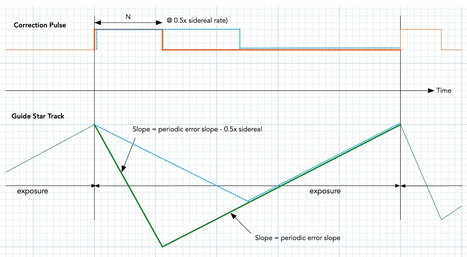
Recall that 0.5x sidereal rate is equal to 3.75 arcsec/sec. Your mounts' slopes probably come in at much smaller number, which means that you probably can choose 0.25x sidereal rate instead of 0.5x sidereal rate to produce a shallower sawtooth, which I superimposed as blue dash lines below to the original figure:
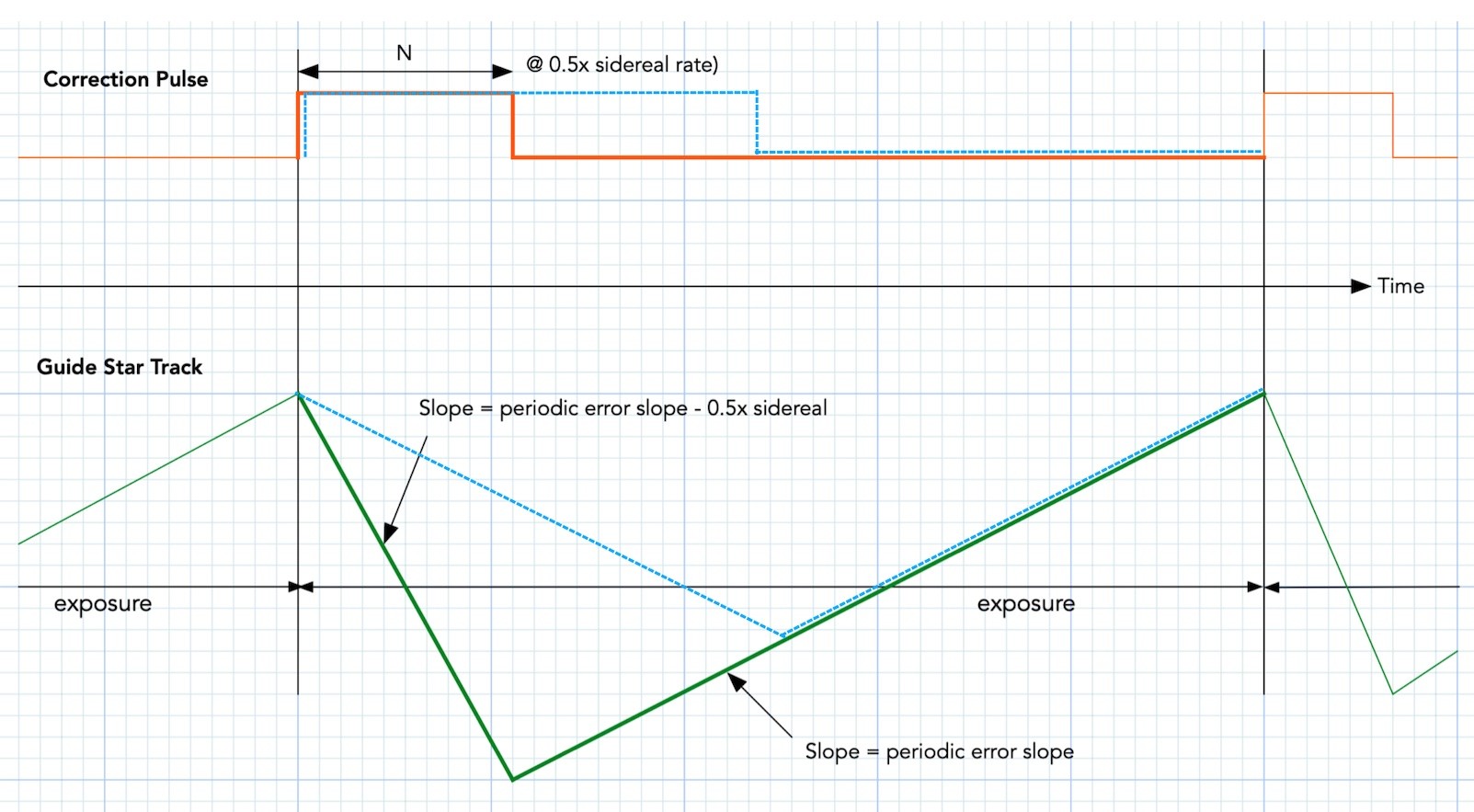
Notice that the dashed blue sawtooth is now flattened (and thus make the guiding even more gentle).
The Max Pulse duration is now double of what you had earlier tailored for 0.5x sidereal rate to match your mount's periodic error slope. But that's OK, since the mount is moving slower when you apply the pulse. The dither recovery is also going to be similar even though the guide rate is lower, because the max pulse duration is doubled.
I should have thought of this earlier, since this approaches the penultimate solution of my "guide by guide-rate" paradigm.
I won't have a chance to try it in the Pacific Northwest Rainforest for another couple of months (with my RST-135) when the rainy season comes to an end. Heck, it just dumped 2" of snow just yesterday morning (although not sticking).
Good luck, and smooth guiding.
Chen
- Edited
One thing that I have meant to address, but hadn't earlier is what do we do with the declination axis, especially for the ZWO mount since only RA axis error in shown on the piece of paper that came with the mount.
For that, I will first refer you to one of Bennett's white papers on polar alignment:
http://celestialwonders.com/articles/polaralignment/MeasuringAlignmentError.html
As an aside, if you are interested in how mounts work, and especially with polar alignment, look up all of Bennett's white papers on the topic, not just the above. The other extremely important resource is Toshimi Taki's seminal work where he solved both how to get polar alignment from the measurement of 3 star positions (modernization of Challis' earlier -- late 1800's -- work) (Chapter 5.5) and how to make a dome opening track a star (Chapter 5.6):
http://takitoshimi.starfree.jp/matrix/matrix_method_rev_e.pdf
Anyway, back to the Bennet's link, you will find Equation (1) that relates the polar alignment error (in arc minutes) to the declination drift (in arc seconds) for a given amount of time (in minutes). I know, confusing mixed units :-) :-).
Note that the worse case cosine of the decination in that equation is cos(0) = 1 (i.e., a star at the equator). If you substitute that in, and changing the time unit to 1 second, you will find the declination drift rate to be less than 0.005 arcsec/second. What that says is that there is essentially no drift in decination when you use a 1 second guide exposure, and if your polar alignment is within 1 arc-minute. Basically, for most people who can polar align to 1 arc minute, you can drop the Max Declination Duration to practically nothing, if not for dither recovery (I usually set mine to 130 millisec and just forget it -- but make your own judgements). Even my old Takahashi EM-11 polar scope can get within a couple of arc-minutes easily.
So, just set it for dither recovery, but keep it small so that, like the RA case, other errors won't be misinterpreted as guiding error. Something about the same or slightly smaller max declination duration than max RA duration would be suitable.
Speaking of which, Taki's document also has equations for the amount field rotation one gets from polar aligment error. Just like Katie Schwertz's document (her Master's thesis) on Optics, Taki-san's document is another must have as a modern exposition of celestial geometry.
Chen
- Edited
w7ay I will attempt to lower the guide rate as you suggested once the skies are clear. The AM5 offers guide rates ranging from 0.1x to 0.9x in 0.1 increments, so I will try using a rate of 0.2x.
I do have one question regarding your post - you mentioned that "0.5x sidereal rate is equal to 3.75 arcsec/sec". However, shouldn't it be 7.5 arcsec/sec? I apologize if the answer is obvious, but I couldn't find where that number comes from.
Thank you very much.
- Edited
fbitto The AM5 offers guide rates ranging from 0.1x to 0.9x in 0.1 increments, so I will try using a rate of 0.2x.
Yeah, just be sure to increase the max RA duration proportionately. The ASIAIR only allows steps of 0.25x increments, and I know some folks are using that. My RST-135 has guide rates in 0.01x increments (two decimal digits).
However, shouldn't it be 7.5 arcsec/sec?
You are right! My mistake. It is 15 arcsec/sec for 1x sidereal (sky moves at ~ 15 º per hour of time). Too many divide by twos for my aging brain :-).
Chen
w7ay Thank you for clarifying that. I appreciate your help.
With the ASCOM driver, it is possible to adjust the guide rate in increments of 0.1x. Currently, I am using a guide rate of 0.9x and a maximum RA pulse of 100 ms. However, I am considering switching to a guide rate of 0.1x with a maximum RA pulse of 900 ms.
Alternatively, would it be better to use a guide rate of 0.2x with a maximum RA pulse of 450 ms?
fbitto Currently, I am using a guide rate of 0.9x
Aha! You might be able to do better by reducing the guide rate (from that blue dashed line example a couple of posts back). At 0.9x guide rate, you are definitely pushing the peak-to-peak sawtooth to be the full slope of the periodic error of the mount.
However, I am considering switching to a guide rate of 0.1x with a maximum RA pulse of 900 ms.
That lenthy pulse may not work well (assuming exposure time of 1 second), depending on what command ASCOM uses to guide.
The ZWO mount can use two styles of pulse guiding -- the first (most commond, since all mounts can do this) is where the computer sends a command to set the direction to East (or West), then turn on slewing at the guide rate. The computer software times the N milliseconds that is needed, and then sends a command to stop the slewing. (Yes, it is this crude, believe it or not. This is why 9600 baud mounts don't guide well because of the command latencies.)
The second style of pulse guiding is where the computer sends a command that says "slew at guide rate for N milliseconds" in a single command (the old LX200 command set does not allow this), and the mount in this case is the one that does the software timing; and command latencies is not in play. (I don't know if ASCOM supports this second style of command.)
Now, if the first style of command is used, remember that you willl need to send E/W (RA) and N/S (declination) slew commands one after another, you cannot overlap the slew commands. If one slew already takes up 900ms, and you are using 1 second exposures, there is no time to finish both E/W and N/S commands.
It might be safer to aim for a guide rate so that you won't need to send a pulse that is longer than 300 to 400ms or so (if you are using 1 second exposure) or 150 to 200ms (if you are using 0.5 second exposure).
If this does not make sense, I will draw up some diagrams. Growing up, English was my third language (learned pretty much after age 11), so I am happier with equations and diagrams, rather than English :-).
Chen (now nearly 75 years old)
- Edited
w7ay ASCOM supports, and AM5 can do pulse-guide - "second style" applies.
ASCOM command is PulseGuide(direction, duration) in DriverAccess.Telescope namespace.
The relevant command in AM5 protocol is
:Mg<dir><amount>#
example :Mgw0125# means "pulse west for 125ms".
Set guide ratio is :Rg0.x0# where x is 1-9 (0.1-0.9 sidereal speed), so granularity is 1/10 of ss (not 1/100!).
RA and Dec PulseGuide() are asynchronous - they may overlap, without delay.
Chen (now nearly 75 years old). As am I My "old" friend. Been AWOL for a week or so enjoying the break from the Connecticut and Jackson Hole Wy weather here in Florida at our home here. I see a lot to catch up on..
Go UConn !!!! AL.
tempus Please do.
OK, we shall start at the sawtooth graph. If each detail of the graph has not yet sunken in, keep studying it. Once you grok it, all guiding problems can be explained away.
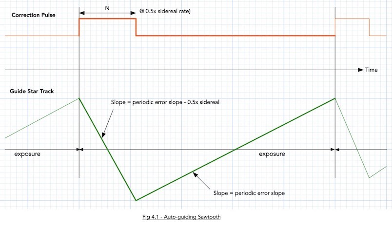
The green part of the graph shows the path of a guide star while you are exposing it. The top red part is the suide pulse.
Notice that the pulse does not suddeny move the mount. It slews the mount at the guide rate (shown as 0.5x sidereal rate here).
Second thing to notice is that the of a guide star will always move (i.e., take the path of that green line). The centroid measurements will always lag the star, and when the periodic error slope is high., this lag makes traditional guiding inaccurate and that is what I am writing the white paper about (to show how to obtain a pulse that corrects in spite of a lagging centroid, and yet be a stable feedback loop -- yeah, you need some rudimentary knowledge of z-Transforms to fully understanf the white paper).
For smooth mounts, the slope of the periodic error is small, and the approximation of using the centroid is good enough.
The guide star will actually move by the the peak-to-peak of that sawtooth.
Now, the leading edge of the sawtooth is a self-inflicted wound! I.e., the reason the green line moves downwards is due to the Correction Pulse. This will cause the guide star to move down at the rate of the guide rate as long as the pulse is being applied. Once you let the foot off the correction pulse, the green line now takes the path that is determined by the slope of the periodic error. This is where the slope of the periodic error comes in -- if you knon't know the worse case slope, you also don't know how much to limit the value N (the max duration of the correction pulse).
Now, if you stare at the leading edge of the sawtooth, you will see that the slope is not precisely the guide rate, but the guide rate minus the slope of the periodic error. This is because the periodic error is constantly being applied, even when we are applying a correction pulse.
Now you can see why shoetening the exposure time (higher guide frae rates) help. When you shorten the expose time, the trailing edge of the sawtooth shortens -- the consequence is that the height of the sawtooth is also proportionately shortened.
That is why, if you have a good guide scope, the first thing you do to strain wave geared mount is to reduce the exposure time to 0.5 seconds! I was emperically playing with my RST-135 a couple of years ago and found that out, but the real explanation did not dawn on me until I modeled the mount dynamics as the above sawtooth (the sawtooth explains everything! :-).
In those days, the ASIAIR was not able to achieve 2 FPS even when you reduced the exposure time to 0.5 seconds, and we could never guide an RST-135 properly with ASIAIR. I pleaded with ZWO, all the way to the top, and the 2 FPS rate was not possible until mid of last year, and I suspect it was because they needed 2 FPS also for their own mount, not because they had wanted a better guiding experience for their customers.
The reason you want to limit the correction pulse duration is bacuse you don't want the autoguider to react to something else that is not caused by the perioid error (just like the shaft encoders will also ignore wind gusts, owls, etc). The autoguider will still react to wind gusts, etc, but at least we now know how to maximally limit the error.
So, two things you can do for now (unless you also enjoy writing code for autoguiding) are: (1) limit the max RA pulse duration, and (2) use the highest FPS guduing as you can get away with (a lot of you know that I don't use an OAG, but have largish guide scopes on the dual saddle plate of my RST-135; and now you know why :-)
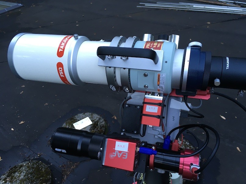
The guide scope is made up of a Borg 55FL objective, and the guide camea of choise so far is the ASI178MM. The dual saddle plate is 10 mm thick, and hides the RST-135 from view in the above photo.
OK, we now go to the third thing that might also help. That "dashed blue line" afterthought that I thought of just a couple of days ago.
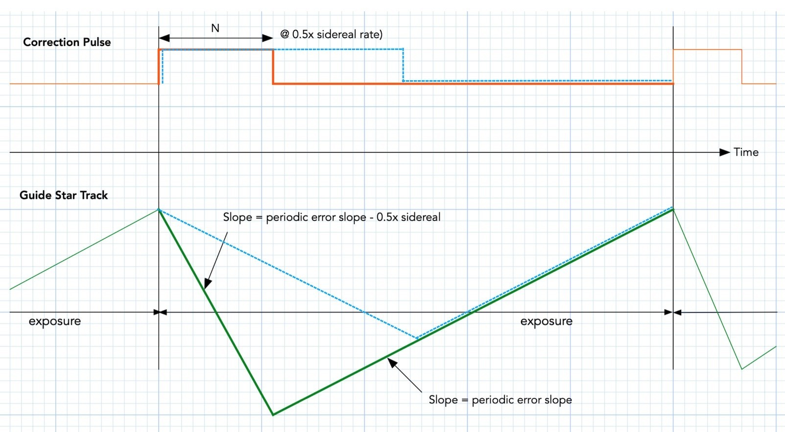
Notice that if we were to slow down the guide rate, we would be stretching the correction pulse (the dashed blue that is superimposed on the red pulse). At the same time, we would be applying a gentler slope to the leading edge of the sawtooth (ah, the sawtooth again :-). Remember what I mentioned above that the slope of the leading edge is not just the slope of the guide rate and the perioic error slope?
Well, look at how it helps us in the dashed blue sawtooth that is superimposed on the green sawtooth -- It has compressed the peak-to-peak value of that sawtooth!
If you stretch the dashed blue all the way to cover the exposure time, the guide rate is now exactly the same magnitude (but opposite in sign) as the periodic error slope of the mount, and you have the smoothest guiding possible -- this is what I have eaerlier pesented a a different guding paradigm, where you are not pulse width modulating the correction pulses, but pulse amplitude modulating the correction pulses.
https://www.elprocus.com/pulse-amplitude-modulation/
Even the worst mount in the world can be calmed down. But as I said, for the forseeable future, you'll have to brew your own code (I have not even formally released my white paper yet -- I can post a like here when it is ready, if there is enough interest -- or email me directly if you want to help proof read it).
Notice in all of the above that the peak-to-peak PE does not ever come into play for auto-guiding (it is only useful for visueal if you want a target to be within the FOV of the eyepiece). Everything with autoguiding is affected time derivatives (slopes). Even down to the guide rate. Find a mount that has small derivatives for the periodic error curve, and you will be a happy person (or just implement the Pulse Amplitude Modulation scheme :-).
Chen
- Edited
Oh, there is a fourth thing to do, and that is to keep the "aggressiveness" parameter low. Don't let it get anywhere near to 1.0 (100%).
This is a simple model of the feedback loop where alpha is the aggressiveness parameter (from my white paper):
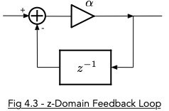
whose transfer function can be shown to be:

Those of you who had taken control theory classes will immediately see that it is a single pole system with the pole at z=(-alpha) in the z-Domain. That means that the loop is unstable at |alpha| >= 1. Those of you who have used large aggressiveness values will probably have seen occasional large oscillations in the guide graphs.
Try keeping "aggressiveness" below 0.5. It will make dither recovery slower, but that can be solved by changing the dither recovery to use faster guide rates, and longer pulses (if you write your own code).
Chen
- Edited
By the way, this is not atypical of what I get when guiding an RST-135 at 2 FPS with the guide scope setup I mentioned earlier, and using very small max pulse durations (150 ms for declination and 180 ms for RA). This is after the ASIAIR finally managed to support 2 FPS at Bin1 on the ASI178MM.
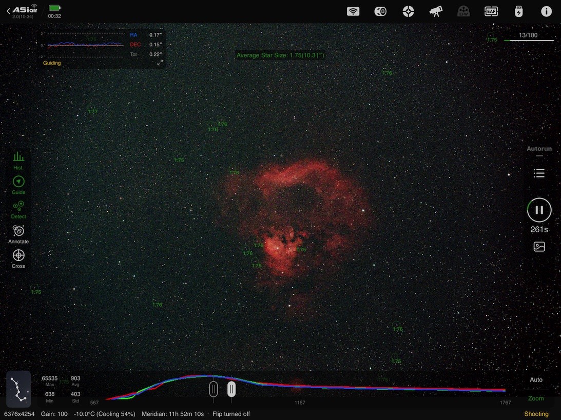
For those who are not familiar with ASIAIR, the guide numbers are in the small floating window that I have positioned at the top left of the window.
Aggressivenesses are under 45%. I practice what I preach.
This shows that @StarzLite 's very first post above is no fluke, as long as you follow the prescribed medications :-).
By the way, this mount has been left outdoors under just a couple of dry bags, 24x7x365 in rain (lots in Oregon) and snow (lots in Portland at the 900' elevation) since late 2020. I am too lazy to polar align, so don't bring the mount or the Mortar tri-pier back indoors :-).
In the image above, the payload was just the guide setup and a short focal length OTA (from the plate scale, you can see the stars are horribly undersampled).
Chen

w7ay Hi Chen Like I said the other day I've been AWOL for a week or so and only now trying catch up on this very interesting discussion.
I must admit there is a lot here for my aging brain to absorb. I also probably have missed or confused some things so forgive my questions if they seem silly.
First like someone else here perhaps in another post mentioned I was having trouble understanding what you exactly mean when you say Slope of the PE... I mean obviously from the supplied graphs of the PE that slope, dy/dx changes over time.
I did see yesterday in another graph you posted someplace here it appears you are essentially graphing a tangent line to that point in the PE curve that appears to have the largest dy/dx.
So as you later say in this post ( forgive me if you have said that in others that I've missed ), what you really are looking for is not the slope of the PE curve, but in fact the slope of that curve at it's worse case point ( largest dy/dx). Once that is known then it is key in helping to determine the N correction pulse duration. Please if you don't mind confirm or correct my conclusion here.
Second, you say: "Now, if you stare at the leading edge of the sawtooth, you will see that the slope is not precisely the guide rate, but the guide rate minus the slope of the periodic error. This is because the periodic error is constantly being applied, even when we are applying a correction pulse".
I'm assuming what you are saying here is that the green line is the resulting slope of the PE as the guiding pulse is added to it and that slope is also a function of the rate at which that plus is added. Again please correct if I am off base.
In addition you say here that "this is because the PE is constantly being applied even when we are applying a correction pulse". I'm not trying to split hairs here but I believe you mean that in regard to the one shot exposure you show in your graph?
In other words. Yes, when speaking of one correction pulse issued at a specific point along a PE curve you would get that resulting graph. However since the PE curve itself is not constant but the N corrections are, each successive graph would look a bit different.
Having said all this reduced to the simplest terms what we are trying to do here is learn how to use the data regarding our mount's known specific PE to tailor our guiding correction pulses in such a fashion so as to not over correct at the worse case PE error.
As I said please forgive my stupidity if I have this all wrong. Al
- Edited
raawe Just wondering what was your sidereal rate when you took that screenshot (0.5?)
Yes, 0.5x sidereal guide reate (and at 2 FPS).
That was before it dawned on me that reducing the guide rate could help a bit more. Although, with those guiding error numbers, just like @StarzLite 's case, I think the limiting factor is something else already -- ptobably the centroid mean estimation in ASIAIR.
My RST-135 has pretty large peak-to-peak PE (somewhere around 50 arc sec peak-to-peak) but has low harmonic distorrtion. If you recall some posts back, the slope if directly related by a factor of N to the N-th harmonic. So, if if you have a large fifth harmonic distortion, it will make the mount harder to guide. If you notice, @StarzLite 's very first post on this thread also shows very reasonable harmonic distortion.
Anyhow, all these problems (even with high harmonic distortion) will go eventually away, even if you just apply a two-pulse-per-exposure algorithm (i.e., just an extra line or two of code). What today looks like a a large sawtooth would be reduced to two sawtooths whose peak-peak amlitude that is halved. Using four-pulses per exposure wil reduce the influence of the slope of the PE curve (where all the harmonic distortion is creating havoc) by 4 etc.
Again, if the 2-pulse-per exposure method is not clea (or to any others)r, I can draw more blue lines to the existing sawtooth to show how it works. Once you see it, the "Aha!" lightbulb will come on and you will wonder why no one in the past has thought of such a trivial solution.
By the way, if I recall (too long a thread to scroll back to look, and my memory isn't what it used to be :-), you are already getting quite decent numbers the last time you posted about it, right? Once you get below 0.35" total RMS error or so, the errors from the harmonic distortion of the mount is pretty much no longer the tallest tent pole.
Again, if the two-pulse solution is not clear to everyone, I can draw it. Just takes 5 or 10 minutes to post an explaination (based on the fact that the second derivative of the PE curve is small :-).
Chen